
The central class of the layout database is the Layout class, which provides a concept for layers, shape containers, cells and hierarchy. Separate from that, a set of classes exist, which represent basic shapes and geometrical objects. While shapes embedded in a Layout object are not independent and care has to be taken when manipulating them inside the database API, the free objects are easy to manage, manipulate and in general to work with as they are normal objects in the script interpreter's context.
In addition, the gometry API provides basic objects such as points, edges and transformations for general use throughout the API. Higher objects such as regions and edge collections provide implementations for geometrical algorithms like boolean operations and DRC checks.
Most classes of the geometry API provide a hash value so they can be used as keys in Ruby hashes.
The Point object represents an integer coordinate in the 2-dimensional layout space, expressed in database units. That object provides the x and y coordinates through the Point#x and Point#y attributes. Points can be added, subtracted, the euclidian distance and its square can be computed using the Point#distance and Point#sq_distance methods. The * operator used with a factor as the second operand will scale both the x and y coordinates.
Next to points there is a corresponding vector class (Vector). A vector is basically the difference between two points. It is meant to describe the distance and direction between two points. The following rules therefore apply:
As points, vectors have an x and a y component which can be accessed with Vector#x and Vector#y. Vectors offer two functions to compute the vector product (Vector#vprod) and the scalar product (Vector#sprod). For some applications it's sufficient to know the sign of the product. You can get that with Vector#vprod_sign and Vector#sprod_sign respectively.
Vectors don't transform the same way than points. On transformation, only rotation, mirror and scaling (if applicable) is applied. Displacement is not applied. This way, the following two forms are equivalent:
(p1 - p2).transformed(t) == p1.transformed(t) - p2.transformed(t)

The Box object represents a rectangle whose sides are parallel to the axes. The coordinates are integer values and express the rectangle's dimensions in database units. The basic specification consists of two points, giving the lower left and upper right corner. The constructor takes either two points (which are ordered internally) or four coordinates representing the left, bottom, right and top coordinates.
A box has a couple of attributes which are shown in the figure above. The Box#area method delivers the area of the rectangle. A box can be "empty" (non-existing). Such a rectangle can be created by the default constructor without parameters. An empty box basically behaves as a region without a point, i.e. testing the intersection with an empty box always returns false. An empty box returns true on Box#empty?. A box whose lower left point is identical to the upper right one contains just a single point. Such a box returns true on Box#is_point?.
A box supports a couple of operations:
transformed(ICplxTrans): returns the box transformed with the given complex, integer-based transformation (see ICplxTrans). Note, that if the complex transformation includes a rotation by a non-90-degree angle (for example 45 degree), this operation does not return a rotated box, because by definition a box has edges which are parallel to the axes. Hence the general solution is to convert the box to a polygon:
# Wrong result
box = RBA::Box::new(0, 0, 100, 200)
transformed_box = box.transformed(RBA::ICplxTrans::new(1, 45, false, RBA::Vector::new))
# -> (-141,0;71,212)

# Correct result
transformed_box_as_polygon = RBA::Polygon::new(box).transformed(RBA::ICplxTrans::new(1, 45, false, RBA::Vector::new))
# -> (0,0;-141,141;-71,212;71,71)
A box object can be constructed from a floating-point object (for floating-point objects see below). Lacking a database unit, no conversion from micrometer units to database units is performed. Instead, the floating-point coordinates are rounded to the nearest integer coordinates:
dbox = RBA::DBox::new(2.1, 3.1, 10.7, 11.8)
box = RBA::Box::new(dbox)
# -> (2,3;11,12)
An integer box can be turned into a floating-point unit box using Box#to_dtype
Floating-point boxes can be transformed using the DTrans, the DCplxTrans or the VCplxTrans transformations. The latter delivers an integer-type box and provides the reverse flavour transformation to "CplxTrans".
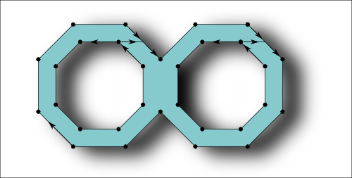
A SimplePolygon object is a polygon that does not have holes. It consists of a single, closed contour. Such polygons are compatible with the GDS2 format for example. A SimplePolygon object can be created from a Box object or from an array of Point objects. Internally, the points will be ordered into a clockwise orientation.
The class method SimplePolygon#from_dpoly creates a integer-coordinate type SimplePolygon object from a floating-point coordinate type DSimplePolygon object (see below). The floating-point coordinates are rounded to the nearest integer coordinates.
The SimplePolygon#bbox method returns the bounding box of the polyon. SimplePolygon#area will return the area of the polygon. SimplePolygon#num_points returns the number of points, while SimplePolygon#point returns the point for a given index. SimplePolygon#points= replaces the polygon by a new polygon with the given array of points.
The SimplePolygon#each_point iterator will deliver each point in clockwise orienation, starting form the bottom/leftmost one. SimplePolygon#each_edge will deliver all edges of the polygon (connecting every point with the next one).
SimplePolygon#compress will remove points that connect two collinear edges. It has a parameter that controls whether to remove reflecting edges (spikes) as well. SimplePolygon#inside? returns true, if a given point is inside the polygon. SimplePolygon#minkowski_sum computes the Minkowski sum between a polygon and another object in various flavors. SimplePolygon#move will displace the polygon by the distance given by the Point argument. SimplePolygon#moved will return the moved polygon without modifying the polygon it is called on (out-of-place operation). SimplePolygon#transformed will return the transformed polygon, either with a simple or a complex transformation (see the description of the Box object and the section about transformations below for a discussion of transformations). Finally, SimplePolygon#round_corners will apply a corner rounding to a copy of the polygon and return that copy without modifying the polygon.
Please note that using the Point-array constructors it is possible to create polygons with self-intersecting or twisted contours. Such polygons may not behave as expected.
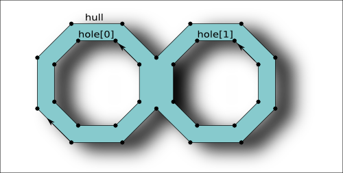
The Polygon object is basically an extension of the SimplePolygon object and in contrast to that object, supports holes. Polygon objects are not compatible with the GDS2 or OASIS format and will be converted to SimplePolygon objects by introducing cutlines when writing them.
A polygon consists of an outer contour (the hull) and zero to many hole contours. The outer contour like for the SimplePolygon is oriented clockwise while the hole contours are oriented counterclockwise. This orientation is established internally. For the API, contours are represented by arrays of Point objects.
A Polygon differs from a SimplyPolygon by providing methods to modify holes and the hull. Holes can be inserted by using the Polygon#insert_hole method. A hole is identified by an index. The Polygon#holes method returns the number of holes. The hole index runs from 0 to the number of holes minus one.
The class method Polygon#from_dpoly creates a integer-coordinate type Polygon object from a floating-point coordinate type DPolygon object (see below). The floating-point coordinates are rounded to the nearest integer coordinates. A constructor is provided that creates a Polygon object from a SimplePolygon object.
Polygon#each_edge will deliver all edges. The orientation of the edges determines whether they belong to a hole or the hull contour. Polygon#each_point_hull will iterated over all points of the hull and Polygon#each_point_hole over the points of the hole with the given index. Polygon#num_points_hull will return the number of points for the hull and Polygon#num_points_hole the number of points for the given hole. Polygon#point_hull will return a specific point from the hull and Polygon#point_hole a specific point for the given hole. Polygon#num_points returns the total number of points.
Polygon#resolve_holes will remove all holes and connect them with the hull by introducing cutlines that connect the hole with the hull. This operation introduces new vertexes and hence may apply some distortion due to grid snapping. Polygon#resolved_holes returns the polygon with the holes removed without modifying the object it is called on (out-of-place operation). Polygon#to_simple_polygon basically does the same but returns a SimplePolygon object.
Using Polygon#assign_hull (or Polygon#hull=) and Polygon#assign_hole the hull contour or a hole contour can be replaced with the given array of Point objects. Please note that it is possible to create invalid polygons where the holes are not completely contained in the hull. Such polygons may not behave as expected. The same is true for polygons with self-intersecting or twisted contours.
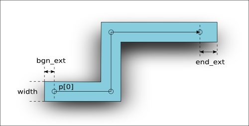
A Path object represents a line with a certain width. The figure above depicts the basic properties of a path. The basic geometry of a path is defined by its spine - a sequence of points that the path follows. By default, a path has rectangular end caps with variable length. The end caps can be round, in which case the extension should be half the path width to avoid paths which are not compatible with the GDS2 format. Round-ended paths return true on Path#is_round?. An example for such a path is depicted in the following figure:
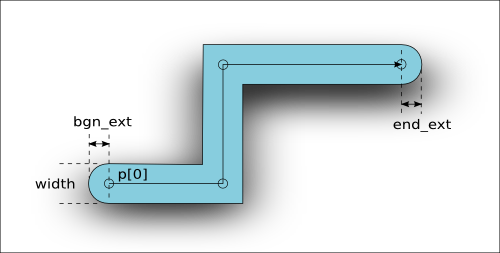
A path with is given in database units. The hull contour of paths with an odd width cannot be represented on-grid and should be avoided. Such path objects are allowed in the GDS2 format, but not in OASIS.
The spine points of a path can be iterated with Path#each_point. Path#num_points returns the number of points. Path#points= allows replacing of the spine with the given array of Point objects. Path#round= sets the "round ended" flag. Path#bbox and Path#area deliver the bounding box and the area, where the area is only approximate and is computed from the spine's length including the extensions times the width for efficiency. For certain acute-angle configurations that value may not be the exact area.
Path#polygon returns the polygon representing the path's hull. Path#simple_polygon returns a SimplePolygon object that represents the hull. Path#move, Path#moved and Path#transformed basically work like for the other objects.
The class method Path#from_dpath creates a integer-coordinate type Path object from a floating-point coordinate type DPath object (see below). The floating-point coordinates are rounded to the nearest integer coordinates.
A Text object is basically a point with a label attached. The extension of a text object only includes the point, not the text itself. For display purposes, a text orientation, font and alignment options can be specified.
The location and the orientation of the text are combined in a Trans object. That transformation can be read and written with the Text#trans attribute. The text orientation is not always shown in the drawing. Whether the text is shown in the orientation specified depends on the application settings.
Font number and alignment flags can be read and written using the Text#font, Text#halign and Text#valign attributes. If one of these attributes is not set, the application-provided default is used. The font is currently just a number and is provided to support the respective property of the GDS2 format. For the documentation of the alignment flags see the class documentation for the Text class.
The text string is accessible with the Text#string attribute. Not all characters are supported. Depending on the format, only a subset of the ASCII character set are supported. Sometimes, line-feed control characters are found in text strings. Following the strict OASIS specification for example, such characters are not allowed. The lower and upper case letters and most of the special printing characters of the ASCII character set are usually safe for use in text strings.
Text#move, Text#moved and Text#transformed basically work like for the other objects.
Passing a DText object to the Text constructor creates an integer-coordinate type Text object from a floating-point coordinate type DText object (see below). The floating-point coordinates are rounded to the nearest integer coordinates.
Edge objects are basically connections between two points. Edge objects are provided to support special applications and are mapped to zero-width, two-point paths in the GDS2 format. Edge objects are not supported as editable objects in KLayout currently. Edge objects may be created by script and are useful sometimes to represent the output of a design rule check tool for example.
Edge objects however a frequently used as raw objects in various applications, i.e. as one output option of a boolean operation. Therefore, the Edge class provides a couple of operations on edges, mainly tests for the geometrical relationship of two edges and points in relation to edges. An edge also may represent a straight line through the two endpoints of the edge, i.e. for the Edge#crossed_by? check.
An edge is defined by two points: the start and end point. Edge#p1 is the attribute for the start point, Edge#p2 the attribute for the end point. Various properties deliver extensions of the edge (Edge#dx and Edge#dy for the horizontal and vertical extension, Edge#length and Edge#sq_length for the length and the square of the length, Edge#ortho_length for the Manhattan distance between the points). Edge#swap_points swaps p1 and p2 and effectively inverts the orientation of the edge. Edge#bbox is the bounding box of the edge.
Various methods test the relationship between two edges or an edge and a point. See the following figure for a summary of these methods:
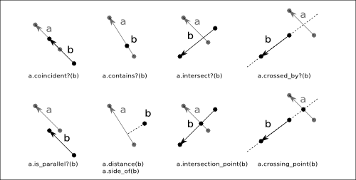
Edge#move, Edge#moved and Edge#transformed basically work like for the other objects. The class method Edge#from_dedge creates a integer-coordinate type Edge object from a floating-point coordinate type DEdge object (see below). The floating-point coordinates are rounded to the nearest integer coordinates.
Beside the integer-coordinate primitives like Box, Edge, Polygon etc., KLayout provides floating-point coordinate variants as well. These objects require more memory and are subject to floating-point rounding issues and are therefore not employed inside the database. They are provided however, to allow a temporary representation of micron-unit objects or for use int the Marker class for example.
The class names for the floating-point variants is the same the integer-coordinate type prefixed with a "D" (for example, DBox is the floating-point variant of Box). Since floating-point variants support fractional coordinates, scaling with an arbitrary value is not connected with a loss of accuracy due to rounding. That is why floating-point coordinates are the target type of general transformations including an arbitrary scaling. For example:
RBA::Box.new(1,1,2,2)*2.5
# -> (3,3;5,5)
# but:
RBA::DBox.new(1,1,2,2)*2.5
# -> (2.5,2.5;5,5)
However, the higher precision of floating-point coordinates comes with subtle issues originating from the finite-precision representation. For example, the value of 0.1 cannot be precisely represented by a floating-point value. The value of 0.1 is approximated and therefore depending on the way it is approximated, 0.1 is not necessarily equal to 0.1. For example (try this in the Ruby console):
a = 0.1
b = 1e-6*1e5
a
# -> 0.1
b
# -> 0.1
# but:
a == b
# -> false!
# the reason is:
"%.21g"%a
# -> 0.100000000000000005551
"%.21g"%b
# -> 0.0999999999999999916733
Because of that, direct comparison of coordinate values should be avoided. The internal precision used is 0.00001. By convention, floating-point type objects are supposed to be used for micrometer-unit objects, hence this precision corresponds to 0.01 nm which corresponds to the tenth of an atom and should be well below physical tolerances.
Some operations which are implemented on integer coordinates (like the removal of holes in polygons) are not available for the floating-point type objects.
All floating-point type objects have a "to_itype" method (i.e. DBox#to_itype) which convert the floating-point type object to the integer-coordinate type object. This method can be given a database unit for scaling from micrometer units. Integer-coordinate type objects can be converted to floating-point type objects the same way through the "to_dtype" method (i.e. Box#to_dtype. A database unit can be passed to this method too for conversion to micrometer units. These methods however require some rounding and are therefore responsible for a potential distortion of the geometry of the object.
For the point and vector object there is also a floating-point equivalent (DPoint and DVector). Both behaves like their integer-coordinate equivalent.
Transformations in KLayout are restricted affine transformations. Shear transformations and anisotropic scaling is not supported. All transformation in KLayout follows the conventions implied by the GDS2 and OASIS formats and include in that order:
For memory performance, a restricted version of that transformation is used if possible. In that restricted version, the rotation angles are confined to a multiple of 90 degree and scaling is not supported. This restricted affine transformation is provided through the Trans class. The 8 possible rotation/mirror variants can be coded in a single rotation/mirror code which is used frequently throughout KLayout (see Transformations in KLayout).
For transforming floating-point coordinates, the DTrans object is provided. The basic difference is that the displacement uses floating-point coordinates (by employing a DVector object).
To support more complex affine transformations include arbitrary-angle rotations and scaling, the complex transformation objects are provided. In addition, the complex transformation object can translate between integer and floating-point coordinate types.
Multiplication of a transformation with an object renders the transformed object:
t = ... # a transformation
p = ... # some point

# compute the transformed point:
q = t * p
Multiplication of two transformations corresponds to concatenation of two transformations:
t1 = ... # a transformation
t2 = ... # another transformation

# Multiplication of t2 and t1 renders an equivalent transformation
# that corresponds to "apply t1 first and then t2":
(t2 * t1) * p == t2 * (t1 * p)
When multiplying two complex transformations, the resulting transformation type will have the corresponding input and output types. For example when multiplying a VCplxTrans with a CplxTrans, a ICplxTrans object will be created. This is because the first transformation takes integers and the second one delivers integers. Hence the resulting transformation is ICplxTrans.
Regions are basically collections of polygons. Regions provide higher functions such as boolean operations and sizing which cannot be implemented on pure polygons because their output may be a number of polygons. A Region is a general representation of a set of points in a two-dimensional area while a polygon is a coherence set of points.
Regions can be created by starting with an empty region and filling the latter with polygons. Regions can also be created from a RecursiveShapeIterator which allows feeding layout data into the region in a very flexible way. In the latter case, boxes and paths will be converted to polygons when feeding them into the region.
Regions feature some important concepts:
The region object is very mighty and easy to use. Here is an example which computes the difference of two boxes (rendering a ring) and sizes the latter:
r1 = RBA::Region::new
r1.insert(RBA::Box::new(-2000, -3000, 2000, 3000))

r2 = RBA::Region::new
r2.insert(RBA::Box::new(-1500, -2000, 1500, 2000))

r = (r1 - r2).sized(100)

puts r
Using a Region object with input from a cell is almost as simple as this. The following example will take the input from layer 11 and 21 from the top cell and the hierarchy below (as is flat) and compute the intersection in layer 100:
ly = RBA::CellView::active.layout

l11 = ly.layer(11, 0)
l21 = ly.layer(21, 0)

r11 = RBA::Region::new(ly.top_cell.begin_shapes_rec(l11))
r21 = RBA::Region::new(ly.top_cell.begin_shapes_rec(l21))

ly.top_cell.shapes(ly.layer(100, 0)).insert(r11 & r21)
A variety of operations is implemented on regions:
Region#&, Region#|, Region#- and Region#^ implement boolean operations (AND, OR, NOT and XOR). The operations can be combined with assignment (in-place) using Region#&= etc. Region#+ adds the polygons from another region to self which is basically the same then a boolean OR.
Region#area and Region#bbox deliver the area and bounding box of the region.
Region#each will deliver all original polygons (unless the region was already merged).
Region#each_merged will deliver the merged polygons.
Region#edges will translate the polygons to edges covering their boundaries. If merged semantics is specified, the edges will only cover the outer edges, not inner ones.
Region#enclosing_check, Region#inside_check, Region#isolated_check, Region#notch_check, Region#separation_check, Region#space_check and Region#width_check implement DRC functions. DRC functions deliver EdgePairs edge pair collections, not regions. Each edge pair marks a violation of the given check.
Region#extents replaces each polygon with its bounding box.
Region#grid_check performs an on-grid check returning edge pairs for off-grid markers.
Region#holes identifies holes and delivers a new region with the holes as filled polygons.
Region#hulls identifies holes and delivers a new region without the holes.
Region#insert adds polygons in various flavors.
Region#interacting and Region#not_interacting select polygons interacting (overlapping or touching) or not interacting with polygons from another region.
Region#members_of selects polygons which are contained in the same way in another region.
Region#merge and Region#merged merge the polygons. This feature allows selecting overlapping polygons (minimum wrap count parameter).
Region#minkowski_sum computes the Minkowski sum of the region with other objects (edges, single polygons and other regions).
Region#move, Region#moved, Region#transform and Region#transformed apply geometrical transformations.
Region#rectangles, Region#rectilinear, Region#non_rectangles and Region#non_rectilinear filter out polygons by their appearance.
Region#inside, Region#outside, Region#not_inside and Region#not_outside filter out polygons by their relation to the polygons in the other region.
Region#round_corners and Region#rounded_corners apply corner rounding to polygons.
Region#size and Region#sized will size the polygons (shift edges).
Region#smooth smoothes out coarse steps of the polygons.
Region#snap and Region#snapped apply grid snapping.
Region#with_angle marks polygon vertices which satisfy a certain angle criterion.
Region#with_perimeter, Region#with_area and many more "with_..." methods select polygons based on their properties.
Edges represents a collection of edges which comprise either full polygons (forming closed contours) or parts of polygons. Edges can be derived from Region objects using the Region#edges
A variety of operations is implemented on regions:
Edges#&, Edges#|, Edges#- and Edges#^ implement boolean operations (AND, OR, NOT and XOR). The operations can be combined with assignment (in-place) using Region#&= etc. Edges#+ adds the polygons from another edge set to self which is basically the same then a boolean OR. Boolean AND and NOT are available between edges and regions as well and will deliver the edge parts inside the given region or not inside the given region.
Edges#length and Edges#bbox deliver the total length and bounding box of the edge set.
Edges#each will deliver the edges in the collection.
Edges#centers will deliver the center parts of the edges.
Edges#enclosing_check, Edges#inside_check, Edges#separation_check, Edges#space_check and Edges#width_check implement DRC functions. DRC functions deliver EdgePairs edge pair collections, not edge sets. Each edge pair marks a violation of the given check.
Edges#start_segments and Edges#end_segments replaces each edge with a part at the beginning or end.
Edges#extended, Edges#extended_in and Edges#extended_out create polygons on that represent the edge with a certain width.
Edges#extents returns a region with the bounding boxes of the edges.
Edges#inside_part and Edges#outside_part return the parts of the edge set which are inside or outside a given region. The effect is comparable to the boolean operations but differs at the exact boundary of the polygons of the region.
Edges#interacting and Edges#not_interacting select edges interacting (overlapping or touching) or not interacting with edges of another edge set or polygons from another region.
Edges#members_of selects edges which are contained in the same way in another edge set.
Edges#merge and Edges#merged merge (join) the edges.
Edges#move, Edges#moved, Region#transform and Edges#transformed apply geometrical transformations.
Edges#with_length, Region#with_angle and many more "with_..." methods select edges based on their properties.
Edge pairs are handy objects to describe the output of a DRC violation. A space violation marker for example will consist of two edges which mark the opposite parts of the space violation. Such markers are represented by objects of EdgePair.
Edge pairs are simple objects consisting of two edges ("first" and "second"). Polygons can generated from edge pairs covering the marked edges and their connecting files using EdgePair#polygon. Edge pairs can be transformed using EdgePair#transformed.
Edge pairs can be "normalized" using EdgePair#normalized. This method returns the normalized version of the edge pair. Normalization will bring the edge pairs in a form such that when connecting their start and end points a closed loop without intersections is formed. Normalized edge pairs will produce nicer polygons later on.
A floating-point version of the EdgePair class exists as well: DEdgePair.
EdgePairs provides a collection of edge pairs and is the preferred output of DRC functions which deliver one DRC marker for each violation.
EdgePair collections can be conveniently split into individual edges using EdgePairs#edges or converted into polygons covering the markers with EdgePairs#polygons. The first and second edges can be extracted as a Edges edge collection with EdgePairs#first_edges and EdgePairs#second_edges. EdgePairs#extents will deliver a region containing the bounding boxes of the edge pairs.